
Introduction
This article started as I rant because BIQU included rubber rucks in the boxes, but no spare fuses. Then I ran into more issues that were Klipper-related, Marlin-related, hardware-related, host-side software related because of the type of the underlying serial hardware, you name it. And I figured since I was so good at rants, I might as well take a shot at making a full walk-through (at least starting from the most recent1 mainboards) of the installation that will also serve as design guidelines for this kind of machines. Special thanks to the Marlin team, they’ve been very helpful and comprehensive.
As a preamble, here’s why I got this hardware : I got a Creality CR-10S Pro that never worked a single time: on the first attempt to print the nozzle dug a deep trench in the bed surface, I noticed after much effort that the Z-axis motors would occasionally lose steps even after I replaced the firmware. So I changed the mainboard with a RAMPS 1.4 board I had at hand but turned out (after hours of configuration and fine tuning) that it was faulty and needed to be replaced. Meanwhile, I blew the touchscreen because I was tired and powered it with 12V instead of 5. So I ordered a Manta M5P, a M8P (for a further project based on a heavily modified, over-priced dual extrusion printer that never really worked anyway) and a TFT35 display. After some two weeks the package arrived, I was happy.
First impression
Wow, nice packaging. Oh, a rubber ducky. Wonder how many there’s gonna be2.
Second impression
Overall, the PCB seems well-designed. Fuses are easily replaceable, nice. They could really have thrown in a bunch of spares though. Plug in the core board in… where are the screws? Missing: ducky doesn’t make me smile that much now: they could really have spared the expense for some fuses, more so that they added a very large number of jumpers caps that are more likely to be laying around and it’s easier to replace the with a little wire than it is to manufacture one’s own fuses.
Third impression
Get on with the manual. Easy to find, then a figure on page 10. A set of vital jumpers in columns of four, and a partially readable caption arranged in five columns. Then there’s information the seems to be redundant but… wait why are some stepper drivers missing the TMC DIAG jumper? No mention of that anywhere. Then there’s this incomprehensible diagram for fan voltage selection with a friendly note on page 14. Fan labelling is obscure. Then upside-down figures (or captions, page 17).
Then there is no table with the description of each connector and pin ; this information is scattered around the text if available at all.
I realize there is not even a packaging slip : bare cardboard, PCBA, that’s all.
Trying to figure out if I have the eMMC version or not. Only information I can find is “取取EMMC,用NORFALSH启启,带TF卡”3 that can be translated (once typos are fixed) to “Get EMMC, start it with NORFLASH, and bring the TF card.” Whatever that means.
At the end of the day, found out I need to click the “Assets” title on https://github.com/bigtreetech/CB1/releases to show the system image I was looking for.
Second day
https://github.com/bigtreetech/sunxi-tools has no amd64 release, so it’s useless. Don’t want to flash something unless I’m absolutely certain I have the correct firmware (eMMC/non-eMMC) and tool. Or is it for the target board? Maybe.
System image is flashed on a microSD (doc says sth like “if there is an SD with CB1, it will be used before eMMC even if
eMMC is present”), sha256 is tested OK after burn to SD media. On HDMI, a pretty BigTreeTech bootsplash then what seems
to be an UI but no mouse or keyboard work. Find out about dtoverlay=dwc2,dr_mode=host ; is it one or two lines? Every
combination was tried, but since the first change there is no display at all on HDMI ; I did get a keyboard light to
work though.
No clue in the manual on how to set a static IP. Config contains lines such as router_ip=8.8.8.8 # Reference DNS, used to detect network connections ; is a router or a nameserver? Who knows, but the confusion of such basic concepts does
not forecast anything good.
Found sample configuration file4. Mainsail still complains. Bored of trying, and at this point I don’t trust these guys any more.
Octoprint
Don’t really want this ; I’ve seen it, it looks pretty and has some cool features for someone who wants to print a companion cube from Thingyverse5, but not quite adapted for my use case.
Gentoo
Keeping just /boot/ and /lib/modules/ from Mainsail, replacing all the rest with Gentoo stage3. Boots. All this
time, the secondary display’s only “useful” information is “Ready” followed by “No printer attached!”. Totally
useless. So far, close to 8 hours spent for almost nothing, and the message from the display only leads me to think
that the “Manta MnP running Klipper” I purchased is actually not running anything (also, the UI on the display is
awkward as shit and I definitely wouldn’t want to use it everyday).
Let’s setup that Gentoo (sigh) and see later for the rest : I need to have an OS setup on the CB1/CM4 because apparently (and I looked at the schematics) there is no way at all to get serial communication to the microcontroller through USB unless I start cutting tracks on the PCB. Very lame.
Gentoo has been compiled and boots properly. So far so good. Setting up distcc and a pretty /etc/motd with toilet
and lolcat (generated from my desktop, because there are a lot of dependencies on the latter) ; not particularly
useful but makes my day happier.
Marlin
Trying to compile Marlin, because I’ve gotten pretty used to it and it seems decent. Quickly
figured out I need to set the CPU to STM32G0B1RE_manta_btt. Doesn’t work as expected: support for the TFT35-E3 display
on this particular CPU is not available, so I’ll be going without any display (again). F* me. I still don’t know if
Klipper6 was pre-flashed on the board, what the parameters are (such as serial baudrate), this sucks.
Documentation is seriously lacking since I couldn’t get the “official” image to be usable on the CB1, there are a bunch
of things I need to configure before anything can be done with the hardware.
Some days later (actually about a month cuz I was busy)
Meanwhile, I’ve been working on my software to generate G-Code (because anything I’ve found is useless for my purpose). Trying to get back at it, I really want to get that printer going (my software is almost ready and I can do some pretty cool things with it already). Updating the text above (it was just a draft and lacked clarity). Reading more doc and blog posts on the web, all of them pretty much useless at this stage.
Powered the CB1 again ; installing more useful tools such as NFS.
Pulled Marlin git repo to be up-to-date ; last time I tried it said this display was not supported on this arch.
Display firmware
Reading the quite long setup procedure on https://github.com/bigtreetech/BIGTREETECH-TouchScreenFirmware ; not sure if this will even work as I have v3.0.1 and the page only mentions v3.0. Also, am I going to have to make cables? Only two of these for the EXP connectors were included, depending on the printer’s mainboard up to 3 are required. Sentences such as “Connect the 5pin serial cable according to the manual of your mainboard” can be found, but the manual of the M5P mainboard (I’ve mentioned it above, it’s bad) doesn’t seem to mention such a serial port. Out of curiosity, I’m taking a look at the M8P motherboard I also purchased ; after a while I realize it’s v 2.0 but the manual only includes versions 1.0 and 1.1, and there have been significant changes (in particular, EXP1 and EXP2 connectors have been removed). The firmware manual has some tables that make it explicit how to connect the display, but again these are jpg images and are not searchable (and there really isn’t a reason for that, an HTML table would have been just fine). Worse, neither the M5P or M8P are mentioned. Considering to post this as a review, the form in the e-mail I received a few days ago that’s here for that very purpose doesn’t work.
With the help of people from Marlin’s Discord, I learn there is an additional repo to the one I was looking at ; quite confusing I must admit.
It’s been at least four more hours of work, and beyond a successful Gentoo install I’m nowhere near being done. As I’m typing this report, I see from the corner of the eye that the display sometimes “sees” random input. Not great. I need to take a break, get a drink.
Yet another day
Learned that with stm32-based MCUs, “the upload function uses a programmer device […] but that also gives you the
ability to accidentally delete the bootloader, it is often unrecoverable”, then asking further that using
STM32G0B1RE_manta_btt_xfer changes upload to uses correct method to copy file to SD card then reboot to install it but
it needs to be running firmware compiled with STM32G0B1RE_manta_btt_xfer before it will work at all.
Managed to flashed Marlin with a very basic config, got communication to work over serial but not quite as expected ; my previous RAMPS board would apparently reset when I connected to it, this board seems to flush the output even before I connect.
Printrun
Since my home-brew program fails to communicate with the STM32, I’m giving a shot at Printrun, more specifically the pronsole component. Some CPU cycles later to compile more deps, I am connected to the printer (rather, the bare mainboard sitting next to me on my desk).
Time to get the display working ; it’s not quite necessary but I’ll take it as an exercise. Or not now : I find it a better use of my time to get Gwiz[^gwiz] to work.
Yet another other day…
GWiz
GWiz, or “G-Code Wizard” in a less condensed form, took some while to get working. The fault to the CDC-based serial connection that re-enumerates every time the MCU is reset, sending useful boot-time messages into the void. It does have the advantage that the MCU doesn’t reboot when connection is established, though. But this is another topic I will hopefully cover some other time.
Hardare installation
Pulled out the previous, definitely defective RAMPS 1.4 board from the chassis: some endstops inputs where defective, and it would frequently spit out nonsense on the serial port. Recycled some of the stepper drivers. The Manta manual doesn’t make it obvious at all what the orientation of the drivers should be. I am glad I also got some fancy brand new TMC drivers that have an obvious orientation in addition to color-coded pins that match those on the Manta ; since the TMC drivers have a clear marking on the pin functions, it’s easy to match the marking on my old drivers. I even decide to keep on the very first modified drivers from my Replicator 2X: this way I can remember which is for the extruder. The microstep chart is unfortunately of very bad quality, barely readable. Also, the color of the frame for the jumper settings differ in both drawings that mention those pins’ functions. Worse still, the labels for these pins are not consistent between both drawings. Still worse (and I’m getting quite annoyed at this point), the tables on the documentation have yet another nomenclature, one for each type of driver ; there are some instructions on how to convert but they ar obscure enough that the symmetry cannot be guaranteed from this source alone.
And another “random” day (so many days XD)
It is time to insert all required jumpers, plug in the stepper drivers, install the mainboard inside the printer case and power it up to do the actual configuration.
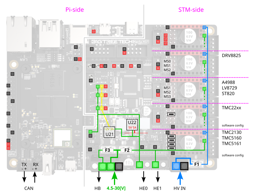
Before I continue, I will add that while reading the official documentation I made my own doc which I believe is much more readable.
And now, I will just copy-paste the e-mail I sent to Biqu regarding the case:
Hello,


I'm so sad. I spent hours reading the doc for my M5P, tested all I could with
USB power making sure everything was connected right, turned on the 24V PSU,
but there was no activity on the board : one driver had a LED, this was the
only thing lit on the board.


I took some voltage measurements, and saw the 10A fuse (F2) had blown.


I disconnected everything that was downstream from that fuse, including all fan
voltage selection jumpers. I even disconnected the endstops ; the only things
that were connected were THB, TH0, the motors and the drivers (and a network
cable).


I then turned the power supply on again, this time watching closely. I saw some
smoke near the FAN0 connector (in red on the photo) and immediately turned off
the power supply.


I took the M5P out of the printer, and tried powering it on USB : it did not work.


I then dismounted the CB1 to test it on the M8P I purchased at the same time :
the CB1 is also dead. I tried powering USB) the M5P without the CB1, nothing
happens.


Considering the facts above, I suspect the M5P must have been defective from
the factory ; I suppose you have some sort of warranty for such cases?


I have inspected the board closely, but I could not see any damage ; I
considered removing the plastic of the FAN connectors to look under it, but
figured it might do some damage and you might want to inspect the board
yourself.


If you want, I can send you the board for inspection ; but since this is most
probably an isolated problem and the shipping costs from Switzerland are so
high, it is probably not worth it.


I hope to hear from you soon,


Best regards


-D


ps: I intend to test powering the M8P with nothing connected except for 24V
"POWER" but to be honest I'm a little afraid after what happened to the M5P


pps: I also attached a drawing I made while reading the doc, because I felt
that the official documentation was tedious to read ; this drawing (it's not
finished, pin numbers need to be added amongst other things) basically replaces
a number of diagrams on https://bigtreetech.github.io/docs/M5P.html ; you are
welcome to use it.
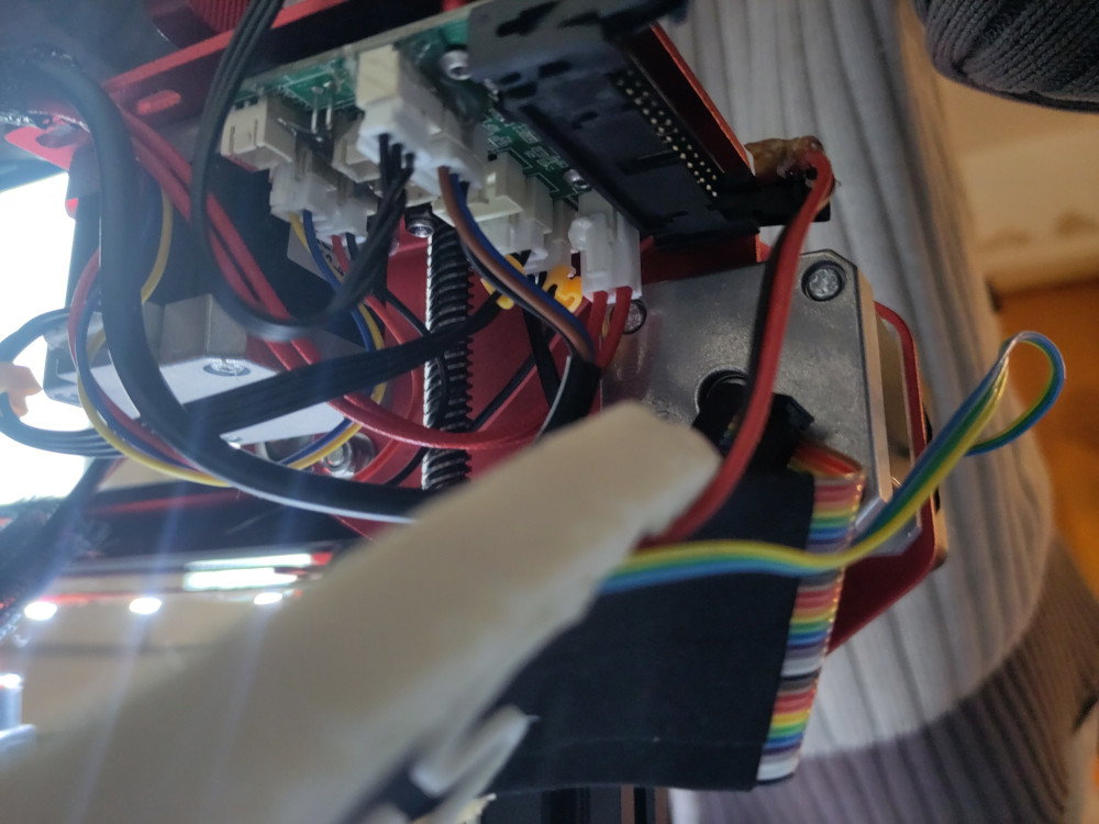
Rewiring everything (this was mostly on a Thursday)
One of the things that was causing me problems was the hotend’s thermistor ; my first thought was that it was defective but connecting it directly to the mainboard proved me wrong : something else had burned, either the flat cable or the secondary PCB that connected to it. Since the wires were too thin anyway, I decided to rewire everything that depended on this flat cable and get rid of it. I made all cables long enough so that the mainboard can sit flat on the table next to the printer (they technically don’t need to be that long, but it is an absolute must that the electronics are accessible when the machine is in a working stance instead of upside-down or lying on it’s side, therefore restricting axes movement and making every single operation painstakingly awkward.
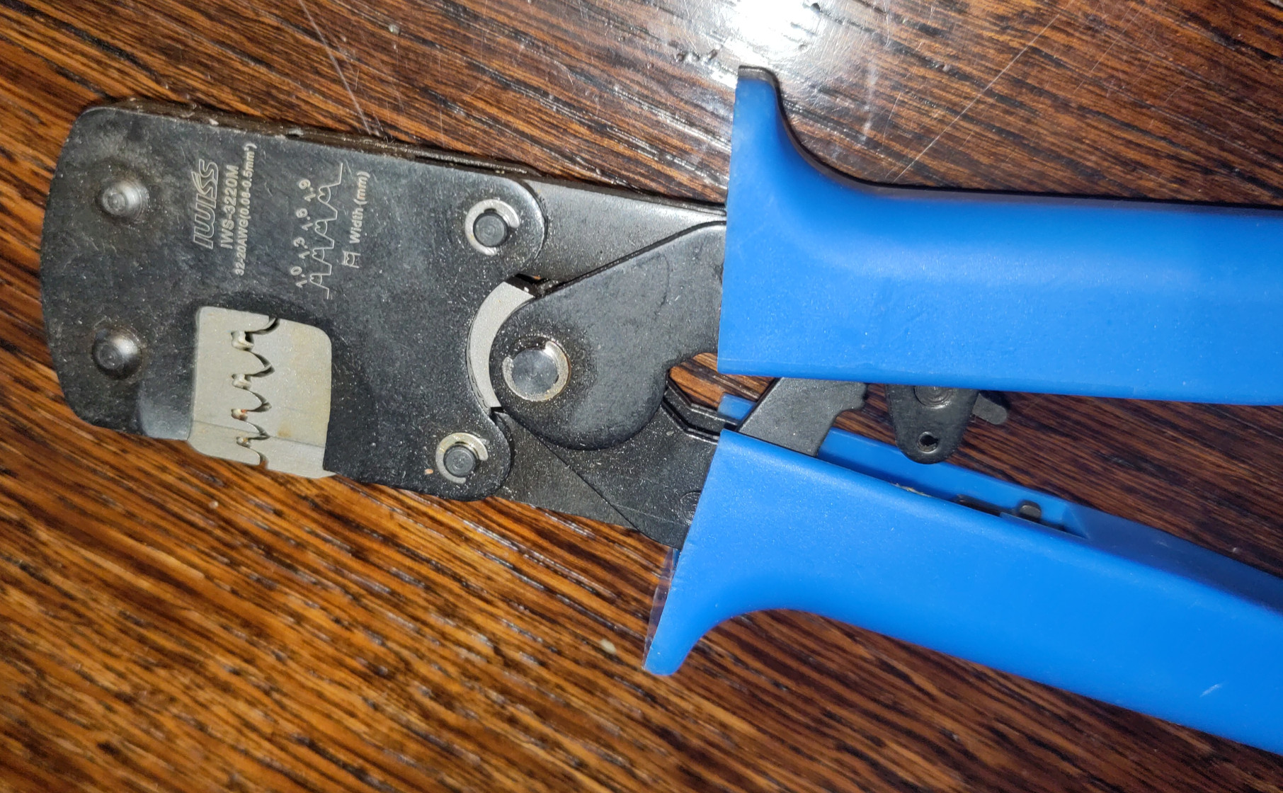
I managed to borrow a crimping tool from the nearby fablab (thanks a lot to those members) : it
is excellent, with a locking mechanism that makes it very convenient : one can put the connector in the tool, tighten it
until the first “click” and it will remain in place. Tool will unlock only when fully crimped (it is also possible to
release it manually with a screwdriver). Reference is IWISS IWS-3220M
I scared myself and I am like “whut?!?” ; after I rewired everything, I turn the power on the there’s a massive amount
of smoke coming out of the machine. Upon investigation, it turns out it was a thin ground wire that I had prepared for
the still unconnected inductive probe, I checked before with he continuity meter and double-checked after and I
stilldon’t understand where such a massive amount of current could have come from. The wire was connected to the GND
pin for IND Or FAN (M8P), and the jumper for VF6 was not even set. Anyway nothing is broken except the wire’s
insulation, all the chips booted as if nothing had happened. There must be a powerful curse surrounding that inductive
probe.
Some message sent on Discord
meeh. can't get my inductive probe to work. maybe it got damaged too by the defective P5M? Anyway I'm somewhat confused by the doc (M8P v2.0):

`ind-dect0.jpg` is from page 8 of the manual
`ind-dect2.jpg` is from page 18 of the manual
`ind-dect.jpg` is from page 3 of the schematic

I guessed the following:
- page 18 of the manual says sth like *"if PNP, short jumper"* which I figure is `JP1`.
- the jumper on the right of `IND Or FAN` (page 8 of the manual) is `P11`
- `Vcool` in `ind-dect.jpg` (the schematic) is `VF6` in `ind-dect0.jpg` and `ind-dect2.jpg` (the manual) ; but why the different nomenclature ?!?
- `IND-DET` in `ind-dect.jpg` (the schematic) is `IND Or FAN` in the manual  ; but why the different nomenclature ?!?

IMHO inconsistent nomenclature is very annoying and may lead to errors ; definitely leads to a waste of time.

between `P10` pins 2 and 3 (`GND` and the input)
- without `JP1` (contact open), I have ~2.7[V] when the probe sees nothing, 0[V] when it is triggered
- with `JP1` (contact closed),  I have "more than 5V" when the probe sees nothing, 0[V] when it is triggered

So apparently I need to have `JP1` shorted, which is good. But I still don't get validation from the firmware, so I
would like to measure the voltage on `R72` ; but where is it?!? Pin 3 of `U17` is equivalent, but the same question
applies: *"where is it?"* I might have more luck finding it, but to do so I need to disconnect everything in order to
examine the board under very good lighting and binoculars (which I am lucky to have and until until very recently)
Moving on
At the same time, BIQU asked to make another video for the rest of the hardware… I’ll do that later.
I found out why the inductive probe didn’t work: at times, the bootloader refuses to flash the firmware from the SD card. I found it depends on minor changes at compile-time such as changing the startup tune. I cannot even hope this is not an issue with the xfer mode, because all it does is basically not require me to change the SD from the printer to the computer and back.
Just before 2 in the morning, I manage to get the first bed mesh since the day I received the printer and it crashed its nozzle in the bed : this was November the 12th or 13th of year 2021… a little more than 2 years, 2 months and 2 days ago. My day has lasted over 17 hours.
Bed adjustment
I needed some sleep. And a break, badly. Done.
Having a bed mesh doesn’t mean the bed doesn’t need to be adjusted. Also, there was this confusion about what Z_PROBE_LOW_POINT would do, and I need to make a PR to update the comments in the config file. Two days ago I did another one because of some obscure and weirdly-phrased error message in the compile-time checks. “Translation is sacred” they say, hell yeah. And I have so many broken or hard keys on my keyboard that I’m actually using two simultaneously : I suppose it’s good for brain plasticity XD.
After some work (almost and entire day) on the host program, logger reports this data:
INFO    ;;Bilinear Leveling Grid:
INFO    ;;      0      1      2      3      4      5      6
INFO    ;; 0 +0.047 +0.055 +0.040 +0.070 +0.040 +0.065 +0.045
INFO    ;; 1 +0.122 +0.138 +0.112 +0.140 +0.125 +0.135 +0.125
INFO    ;; 2 +0.150 +0.145 +0.107 +0.120 +0.100 +0.135 +0.130
INFO    ;; 3 +0.130 +0.110 +0.062 +0.075 +0.045 +0.080 +0.082
INFO    ;; 4 +0.012 -0.007 -0.062 -0.060 -0.093 -0.057 -0.032
INFO    ;; 5 -0.160 -0.190 -0.242 -0.233 -0.267 -0.230 -0.205
INFO    ;; 6 -0.360 -0.387 -0.455 -0.450 -0.492 -0.447 -0.410
It confirms what I thought when I was learning about Z_PROBE_LOW_POINT: the bed is tilted towards the back ; not that much, but still the equivalent of about 1-3 layers so it is definitely worth fixing. With the current mesh parameters, the corners are right above the bed levelling screws which are M4x0.7, so half a turn back left and almost 4/7 of a turn back right ; I’ll then heat the bed to 80°C and probe the mesh again for verification and another iteration if that is required.
Second run
;; Bilinear Leveling Grid:
;;       0      1      2      3      4      5      6
;;  0 -0.192 -0.130 -0.110 -0.065 -0.097 -0.095 -0.140
;;  1 -0.020 +0.050 +0.052 +0.093 +0.082 +0.075 +0.037
;;  2 +0.065 +0.120 +0.112 +0.132 +0.112 +0.132 +0.105
;;  3 +0.120 +0.155 +0.135 +0.160 +0.135 +0.155 +0.130
;;  4 +0.047 +0.087 +0.065 +0.082 +0.052 +0.075 +0.072
;;  5 -0.072 -0.040 -0.062 -0.040 -0.065 -0.047 -0.040
;;  6 -0.242 -0.200 -0.227 -0.203 -0.242 -0.207 -0.192
Two corners are at “exactly” the same height (M48 Z-Probe Repeatability Test reports a delta of 0.002 with standard
deviation of 0.001225, so not bad), then one is a little too low and one a little too high, I’ll give it a tiny fix and
tighten the lock nuts. We can also clearly see that the bed is somewhat dome-shaped : this is expected because I added
insulation under the bed (this halved the heating time) and desirable because of part retraction ; I would have
preferred to have about half the current delta between the center and corners, but that will do. I obviously set the
origin at the center of the bed although it is not a standard practice for Cartesian robots : IMHO if definitely makes
more sense not only because of the intrinsic shape but also the temperature distribution on the surface : currently and
as the bed is cooling down, the firmware reports 55°C ; with an IR thermometer I measure 49°C at the center and only
34.4° in the corners. I did try to compensate for this deviation by adding more heat-conductive tape on the edges, but I
should have added more in the corners : it would be interesting to run a simulation in order to determine the ideal tape
pattern to use.
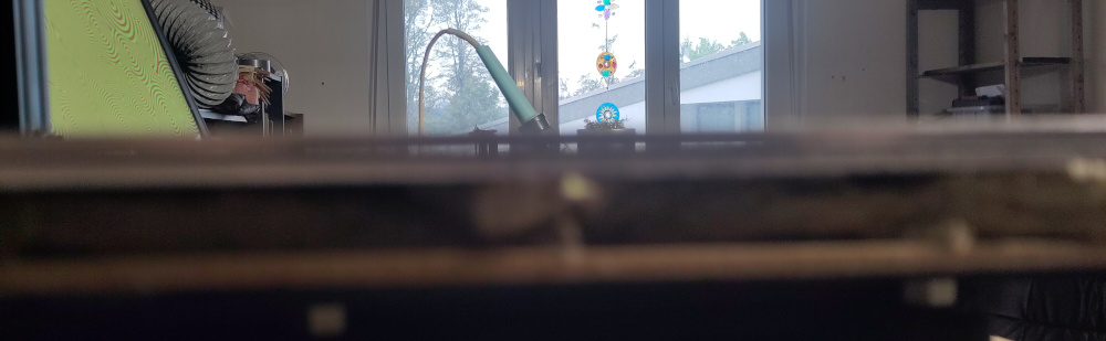
Above picture shows there was quite a lot of space between the heating element of the bed and the aluminium layer on which the print surface was glued. Below, I got rid of the clamps and used heat-conductive adhesive tape to secure the aluminium plate.
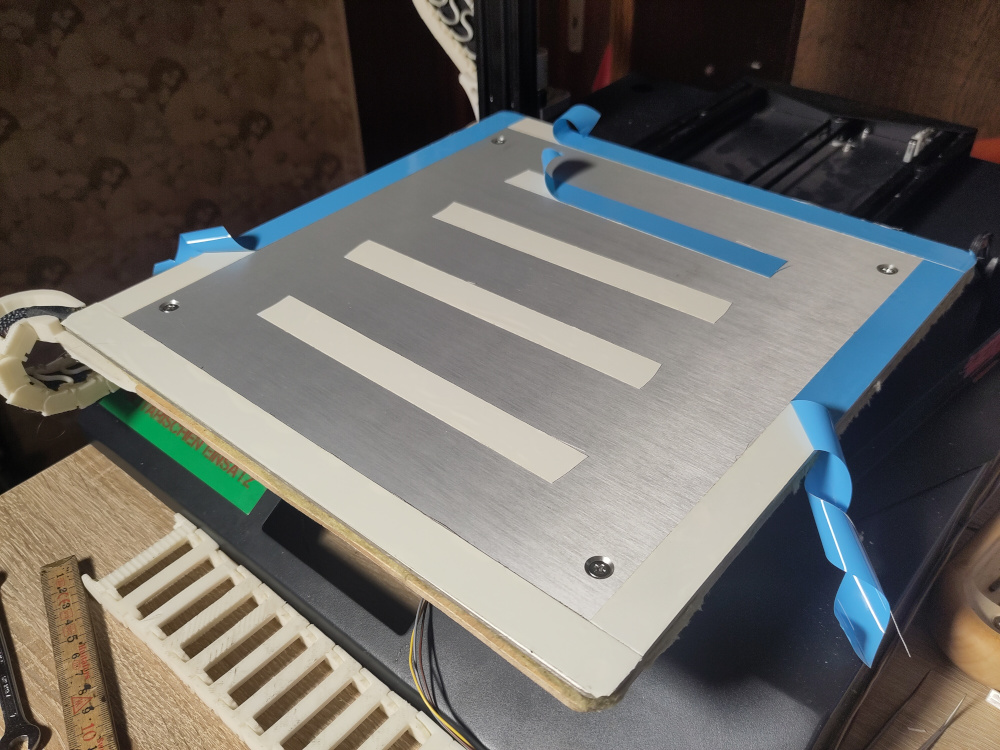
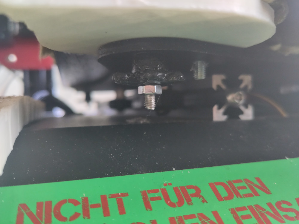
As you can see below, I also trimmed the original adjustment wheels, one of which would originally turn a little bit every time it went past the heatbed cables, slowly loosening it ; these large adjustment wheels are dinosaurs from the era where bed probes did not exist and more-than-daily adjustment was required: nowadays this makes very, very little sense. Once they were cut, I used a lighter to apply a little (sometimes too much) heat to make them smoother to the touch.
Extruder hell
Now that I had the motion and temperatures working fine, time to configure the extruder. Easy, right? Well not so fast… because it turned out there was slippage on the filament, and I really couldn’t extrude fast at all. So I got rid of the original Creality extruder which didn’t look that bad at first but only grabs the filament on a single side - something I will avoid at all costs from now on.
Design from Brazil
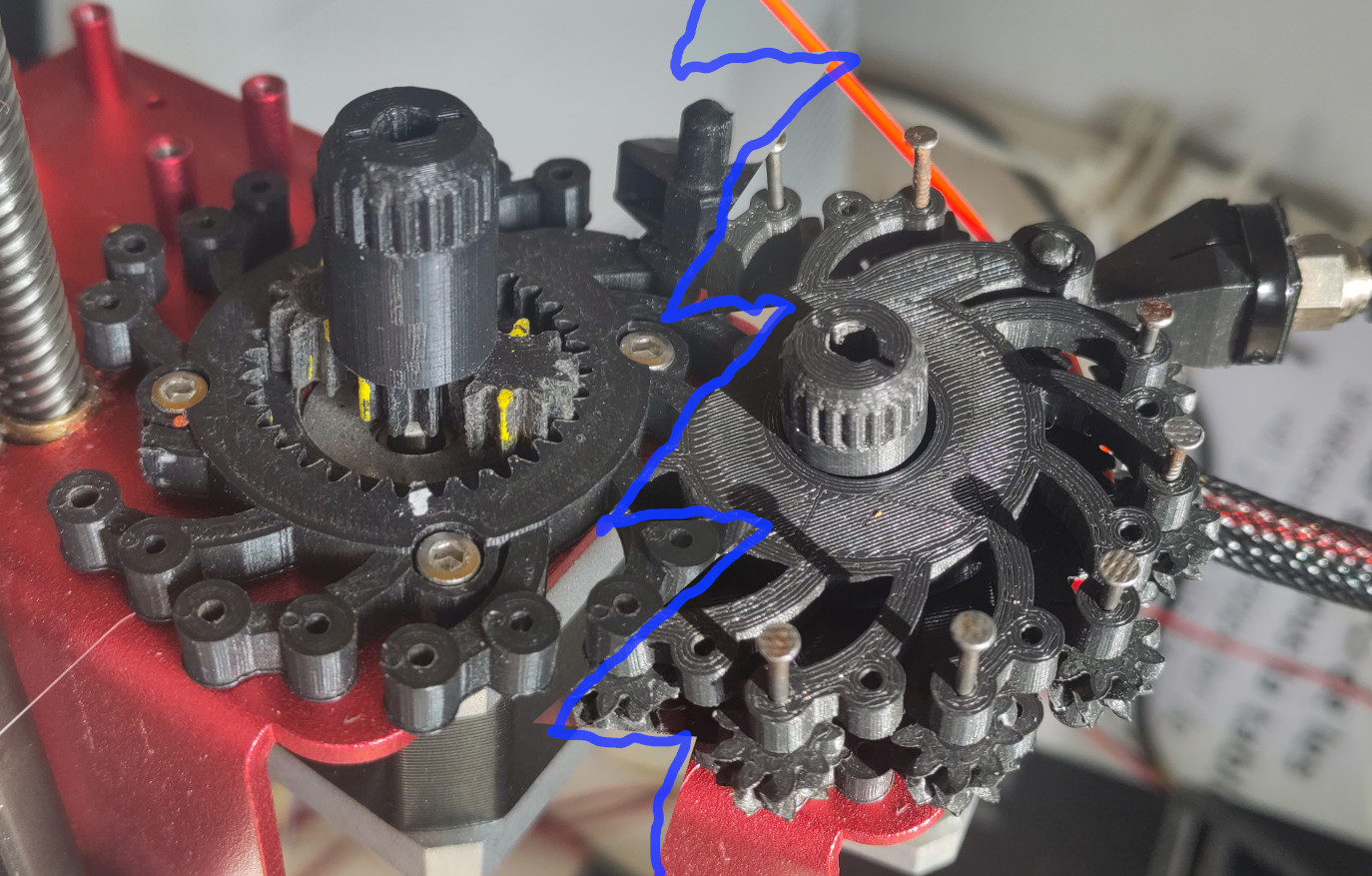
So I tried this extruder of Brazilian design laying around, 3D-printed at the fablab : this design is pretty good, because it relies on plastic-plastic friction on a large surface area and requires almost no special parts. But the drawing was really bad: the included planetary reductor had only two satellites, they had way to much play and the thing would lock with little to no torque applied to it ; I remember it was not parametric (only STL files) and I could not remember the name of the thing - nor was I able to print another one. So that was a no-go. I tried making a washer on the lathe to make sure the satellites would remain horizontal, but that didn’t help ; unfortunately this was a no-go (but I still like the design that just needs to be drawn properly).
Makerbot recycling
I still had the dual extruder setup from my old Replicator 2X: it had exhibited the slippage problem from day one, and I knew I couldn’t use it as-is. But I had two almost identical extruders, only symmetric (which turned out to definitely be a feature) : so I would juste use them in parallel on the extruder driver, and in series on the filament. I found a few pieces of plastic found in the trash a few years back, made my choice and started building them mount.
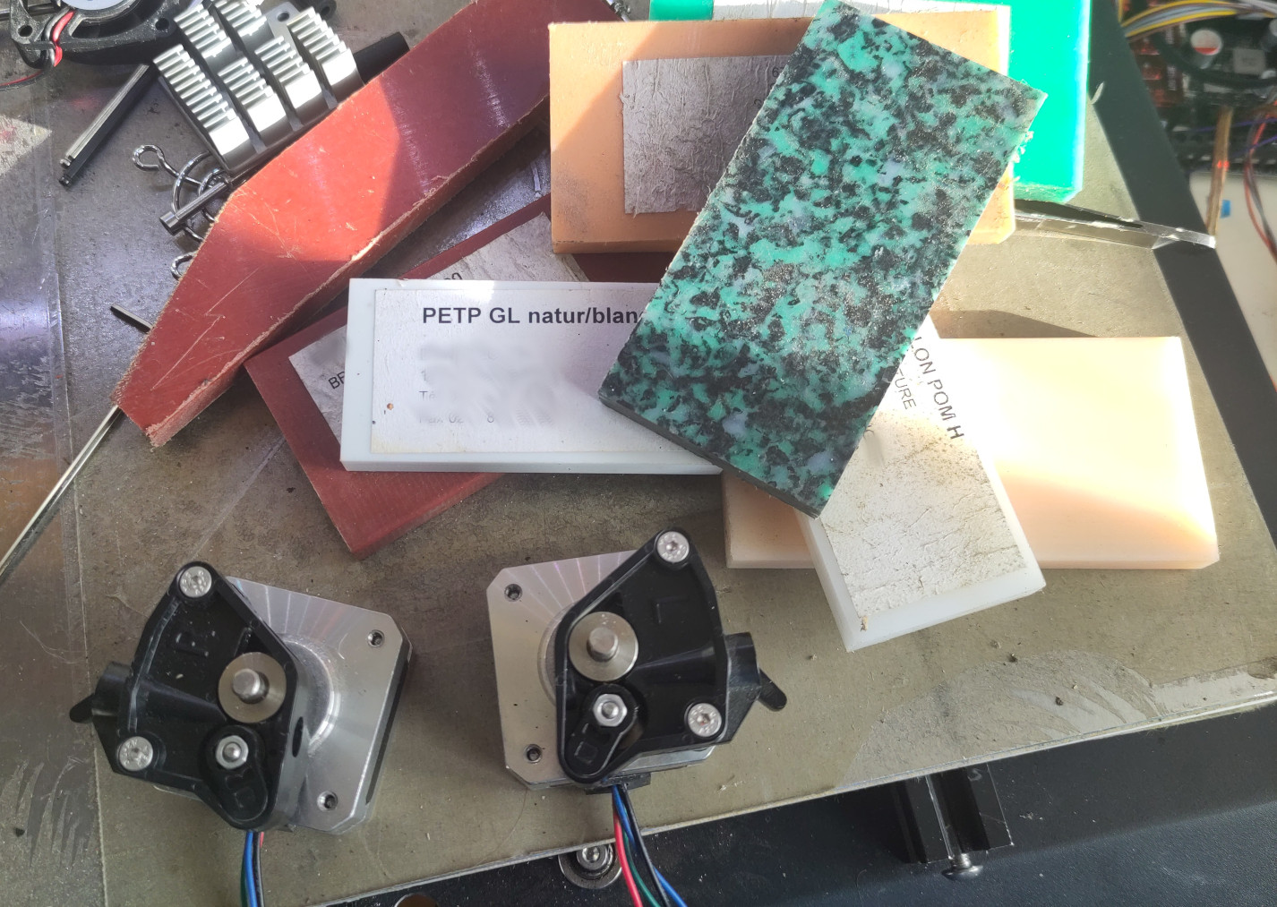
That went pretty well, and after just a single cut, a few holes, some filing work and about an hour I had something quite satisfying that used the two smallest motors I could find:
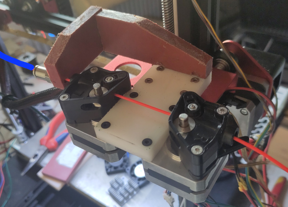
At his point slippage didn’t seem to be an issue, but as I pinched the filament to make some resistance the motors would start to oscillate and not move anymore. So I tried with larger motors : this didn’t change anything. So I tried wheels with slightly different diameters : this didn’t help either.
Stepper motors in parallel on a single driver
Then it became obvious that it one must never ever put two motors in parallel on a single driver: the combined torque is not more than 20% of that of a single motor, and this explained why the original CR-10S Pro setup was losing steps on the Z-axis. On Marlin’s Discord, I also learned that a lot of printers are setup that way ; many boards - including the new Manta M8P, have at least one double-motor connector on a single driver. Seriously, don’t do that: instead, use a synchro belt. Two motors on a single driver don’t even allow for alignment by the firmware, so it’s pretty much the worse thing you can do on a printer: it will ruin everything else.
Two steppers in mixing nozzle emulation
My first idea was to pretend I had a mixing nozzle with twice the filament flow: this worked really well but was a pain to configure (existing gcode had to be post-processed, or the slicer had to be carefully configured) and prone to errors and random problems with retraction and oozing prevention. But it proved to be mechanically reliable and I learned some stuff what would be useful for later ; then I went to sleep.
Next morning, I woke thinking “why didn’t I think about this before?” and you may have guessed what that was: piggy-backing! For those who don’t know, it’s an ancient technique frequently used when dealing with 74xx series components (and others) that were lacking sufficient output and would periodically burn out.
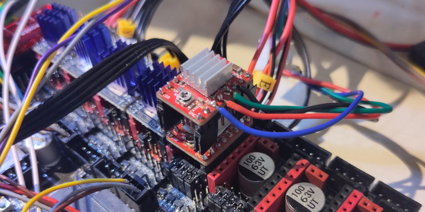
Beyond a faulty solder on the clock line that confused me for a little while, this went really well : you must however be aware this
only works with passive drivers such as the A4988 that only eat dir/step signals ; those like the TMC2209 that do
bi-directional communication over an SPI line or similar are likely to crash badly. Then I learned there is the option in
Marlin to use double drivers for the first extruder, just like for the Z-axis : I decided to stick to my piggy-backing
nevertheless, because I find it cooler and it doesn’t use as many driver slots on the mainboard.
I then also added a bit of PTFE tube inside some copper tube between the extruders: the one closer to the nozzle would slip, but this was expected.
Sub-hell: flashing
While I was struggling to get the extruder to work, I ran into another issue (again): the bootloader would sometimes not eat the firmware I wrote on the SD card, and this got really, really annoying. It took me about an hour an a half to figure that with a smaller partition on other, larger SD card, that went better. Don’t ask, I’ll just blame it on the curse for now.
A few days later, while re-using that SD card in order to duplicate the OS so that I can upgrade it on a Pi4 while still being able to print, dmesg shows
[11615.177042] sd 8:0:0:0: [sdd] 31116288 512-byte logical blocks: (15.9 GB/14.8 GiB)
[11615.179224] sdd: detected capacity change from 0 to 31116288
[11615.410161] sd 8:0:0:0: [sdd] tag#0 FAILED Result: hostbyte=DID_OK driverbyte=DRIVER_OK cmd_age=0s
[11615.410166] sd 8:0:0:0: [sdd] tag#0 Sense Key : Aborted Command [current]
[11615.410168] sd 8:0:0:0: [sdd] tag#0 Add. Sense: Data phase CRC error detected
[11615.410170] sd 8:0:0:0: [sdd] tag#0 CDB: Read(10) 28 00 00 00 00 00 00 00 08 00
[11615.410171] I/O error, dev sdd, sector 0 op 0x0:(READ) flags 0x0 phys_seg 1 prio class 2
[11615.410174] Buffer I/O error on dev sdd, logical block 0, async page read
[11615.699864]  sdd: sdd1
which may explain why the bootloader was not happy. Curiously enough, I didn’t see this before though.
Temperature readings hell
So another night went by, I cleaned up the workshop that had by then become a terrible mess and before I tried to actually print anything I set myself to film that video BIQU had asked for relative to the warranty of the components that had failed along with the M5P. So I did this, and it went well.
Then I replaced all other known good components on the board, and initiated a bed levelling mesh. After a short time, the printer makes some clicking sounds on the speaker and throws a heating error: I try again, and it turns out the bed doesn’t heat up that much. In the intent of checking the wiring (which had been fully done recently with a lot of care), I unplug the LCD, invert the temperature probes, check again.. still fails. Bed heating is definitely dead.
Aargh. How deep is that flaming hole? Am I ever going to hit the bottom?
I plug the display back in. Mainboard shuts down. Turns out I plugged it in the
wrong port, I’m not really surprised at this point (but upset with myself):
GND and +5V are inverted there. I turn off the power supply, plug it back
in, turn the power on again. The display complains that no printer is
connected. I try to connect with the host software, it seems there is no data
received on the serial line. Really? After trying a few things I realize I can
home the printer, move the axii around, query for parameters. But I completely
lost the temperature readings. The display still doesn’t connect anymore, I
must have broken some pins on it or on the mainboard (although, looking at the
schematic, I don’t really see why). Never mind. I could complain with BIQU that
the tests they made me do broke the bed heating, but I definitely messed up
afterwards with the display ; since everything else works, I’ll use the board
on a machine that doesn’t require heating.
Waiting for replacement parts
The people at BIQU were nice: I mentionned I needed some extra parts and suggested they ship everything together. This allowed me to get a PEI printing surface, one of their latest extruders, the last in stock not-yet-but-soon-to-be-released filament sensor that goes with it ; I didn’t save anything on the shipping fee since it would have been free anyway but apparently BIQU used expedited shipping because less than 6 days after the parcel was sent it was already in Zürich airport. On a saturday morning, when the customs- and freight-related people apparently don’t work. This leaves me some time to tend to other projects - not something I need to search far or long for.
Pas pendant ce temps (deux jours plus tard), pas à Vera Cruz…
Tracking hell shows up. Not that I never experienced that, no. Around 12:30 on Monday I check my e-mail and see a notification from DPD saying they received a parcel. 17-track.net that I had been using until then still shows nothing about it ; it will be updated some time later saying that my parcel was handed to DPD at 12:12. Try to do some sort of autentication, DPD’s website tells me I need an SMS verification code: if they have any number, it’s on the fixed line that can’t receive SMSs. I can see more details with my post code, but to change anything it keeps on asking me for the SMS confirmation.
As I step out for an appointment, I notice a small package near my mailbox. Really? I throw it inside, I will look at it later. When I do, I find a new M5P, with yet another rubber ducky. Still no spare fuses (I really wasn’t expecting to) but not replacement drivers nor CB1. Will it be in the other parcel that is still in transit? I quite doubt so, but I’ll wait. First thing I do is test the board on the lab power supply (which I didn’t have back then), first at 12V, then 24V. Seems fine.
For the sake of it, I’m going to try powering on the old board again : applying 24V on DCIN, I see D6 get slightly
bright and fading down ; the power supply reports less than 5W power. No smoke near the FAN1 connector as I expected.
I smidge the board with isopropyl alcohol and power it back on: it is obvious that U25, a ME6211C33M5G regulator, is
heating way more than it should. I like that alcohol trick. Since the board is dead anyway, I take the time to measure
the 5V bus: 5V. For the sake of completeness, I try with the CB1 plugged in, and power it this time through USB : only
1.9V. I stop the test and as I reach to unplug the CB1, it’s gotten real hot, like 80°C. Now that is abnormal. Without
it, 5V goes back to 5V ; but still no D6. As I do a few more “random” tests, I notice that with 12V applied on DCIN
things seem pretty much normal but with 24V I always get a noticeable spark when I apply the power.
Installing new M5P
Installing the new M5P went really well: since all the cables and connectors were perfect (except for the original speaker from the CR10 that has wires that keeps on breaking at the connector), sice I know the MxP family relatively well by now, there really weren’t any surprises. I turn the power on, LEDs got bright, ssh connects to Gentoo on the CB1 ; time to configure the pins for this (hopefully) final setup.
Configuring the latest board took just a few minutes (at least for the first part), followed by a quick compilation. Flashing LED blinks, then both status LEDs next to the MCU are solid red, I’m pretty sure only one should be on. Weird, but whatever. I go back to my desk, get some temperatures. Try to home, Z makes a bad noise and I wonder if motors are turning against each other ; that would be weird.
Hopefully the “last” day
Tracking nuisance
Typically a rant: “Tracking a package on DPD’s website? Simply reload the page to update the info? Well not that easy my friend, cuz DPD really tried saving costs on their webmasters” ; so yeah when some sort of cut-and-paste is required when there is technically no reason at all why the user should be bothered with that, crap.
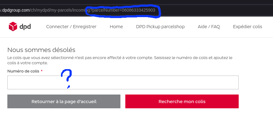
Another thing that is really annoying, those package tracking websites only mention the day of delivery, never where the truck is, not even approximately: so many times I’ve had to stay at home waiting for a parcel and didn’t get it because the driver didn’t bother ringing the bell, calling the phone number that is set in plain view, or even reading the name on the mailbox, sometimes I feel like waiting in front of the door until the person shows up. Or… don’t they? as I reload the page I see a little truck icon on the map. Now that is a relief, but it doesn’t update automatically. Come on… Lookig at the delivery details, there is now a one-hour window for the expected delivery time. So they fixed that too, cool. That really wasn’t a rant after all then.
Driver mishap
Unscrewed one of the threaded rods from a driver, noise is gone but steps are wrong. One motor is running faster than
the other: I am advised to issue an M122 command to check communication with the drivers: one shows Error: All LOW.
I’m in the process of upgrading GCC on the CB1, but I really don’t feel like waiting until this is done to power off the
board. Someone on Marlin suggests cutting a trace on the PCB so I can power off the MCU independently , it could be an
idea and definitely a suggestion for future versions, just like microswitches to be able to connect the MCU directly to
a desktop computer’s USB ) but I’m not going to do that unless I have the Gerber files - which I obviously don’t. Only
God and a handful of chinese know about that, so full shutdown it will be (I really don’t want to wait for this lousy
CPU to compile GCC which it will fail to do anyway because 1GB really isn’t enough).
Swap the drivers, reboot. M122. Same error, on the same driver slot. Jumpers are setup the same, so somehow the M5P is
defective. Copy the firmware files to the CB1 so I can update it with xfer ; pip cannot install module heatshrink2:
back to copying the files on the SD card and moving it back and forth between my workstation and the printer. “Good”
news: using the slot previously used for the extruder stepper works. That fixed, I try to home: fail. Diagnose with
M119: z_max is reported instead of z_min, z_min is not. At times like this I feel like setting myself on fire, but not
quite yet: I have to wait for DPD to bring the other parcel.
Comparing the configuration files (I had it working on the M8P), I find out I have to do this:
-#define Z_STOP_PIN                   Z_DIAG_PIN  // MIN4
+#define Z_STOP_PIN                   PC15  // IND-DET (with adjustable pullup set via jumper)
+#define Z_MAX_PIN                    Z_DIAG_PIN  // MIN4

 //
 // Z Probe (when not Z_STOP_PIN)
 //
 #ifndef Z_MIN_PROBE_PIN
-  #define Z_MIN_PROBE_PIN                 PC15  // IND-DET (with adjustable pullup set via jumper)
+  #define Z_MIN_PROBE_PIN                 Z_STOP_PIN
 #endif
The "(when not Z_STOP_PIN)" sentence is really misleading, IMHO just like the use of *_STOP_PIN instead of using
MIN and/or MAX that would remove the need for the somewhat obscure *_SAFETY_STOP definitions in Configuration.h ;
I’ll leave this for someone else to argue about that and/or fix it.
Looking at the position of the delivery truck, it has suddenly vanished from the map. Did I miss it? is it already gone? No parcel outside. Parcel status still not delivered. Since it’s half pas 12, my guess is the driver went for a byte to eat in a parallel universe and should be back soon.
Defective EEPROM hell
Right, the title was a spoiler. Anyway.
So far, I’m happy. I heat up the bed, run a leveling mesh. So far so good. Save the mesh with M500: connection lost.
Try some simpler thing, like simply restoring default settings and saving them, same thing: MCU reboots and
re-enumerates each time. Dust advises me to set #define WATCHDOG_DURATION_8S, which does indeed double the time
before the MCU re-enumerates but doesn’t fix the EEPROM issue.
I got yet another defective board, and that’s beyond the mere nuisance of the faulty driver slot.
Cup of tea, then.
Parcel is here
The dude in the DPD truck didn’t even have to cross the road: I was waiting. Parcel is neatly packed in a volumetric-efficient way; printing surface is way heavier than I thought. There is a 0.8mm-thick spring steel sheet, a magnetic sticker, but nothing that looks like a PEI printing surface7. And the cardboard packaging is just a little too small to fit the surface.
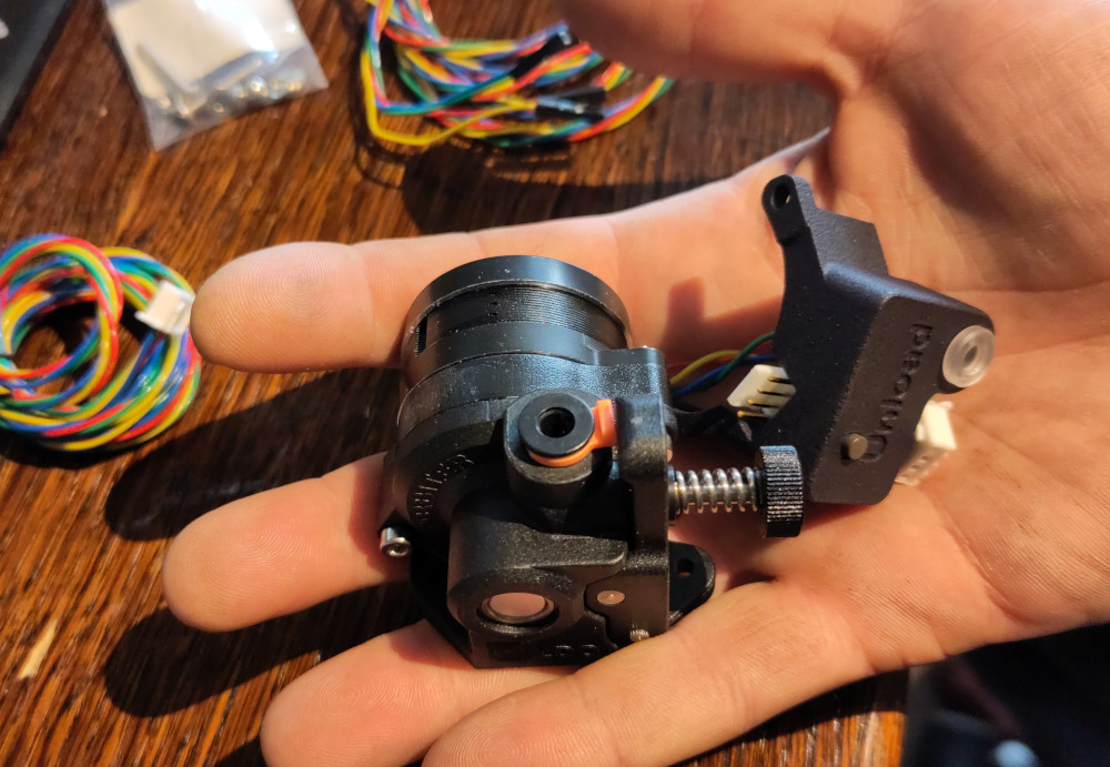
Then there is the extruder motor and filament sensor. Much smaller than I thought, a total of 155 grams on the scale, and really nicely built. Filament sensor is open hardware. There is a booklet tat explains in detail how to configure the firmware. No instructions on how to install it on the motor, but I quickly figure out the steel ball that is added to the replacement screws is a spare to sense the filament and that the thing to keep the PTFE tube in place just needs to be pulled out. I’m disappointed that the sensor only senses the presence of the filament: this wasn’t specified anywhere in the BIQU shop (and they obviously didn’t give the link to the documentation and full sources).
Ducky usage
At this point I now have 6 duckies total, of which only one is healthy: one can bareley squeak both ways and the 5 others can only do so when the air is flowing inwards or outwards if at all. I don’t like throwing things away unless there really isn’t anything left to do with them, and having them hanging around around my desk is not an option.
Since these duckies are useless and pretty dumb (in the literal sense), I’m going to give them a purpose in life, remove the faulty squeaky-thingy and shove a Neopixel up each of their bottoms ; wired together with a bit of transformer wire and secured to the top of the printer frame with hot glue, they will make a perfect multi-purpose indicator.
Remember how fighter pilots painted symbols on the airplanes for every enemy they shoot down? My duckies are same-same: I first named that printer CR-whale because it was Creality but the firmware was Marlin (and Marvin, and…) then since I removed pretty much everything that was Creality I renamed it to a simple whale. Turns out it’s a killer whale that eats ducks (and mainboards), so I’ll have to rename it once again.
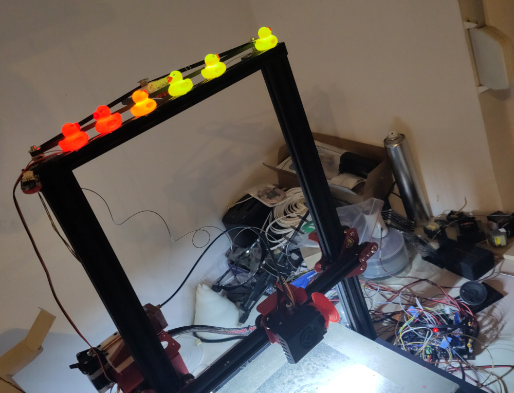
Above, you can see the synchro belt that is not really needed anymore (but it really doesn’t hurt, on the contrary), the mainboard and speaker laying on the table, andquite a bit of mess that is waiting to be dealt with, the Z-max endstop that is totally not where it should be and next to it, of course, six glowing rubber ducks that finally make me happy when I see them. There is also a permanent 24V white LED lighting (recycled from wherever) that makes it obvious when the power is on and lights the work surface really well.
Chinese New Year & Spring Festival
At this stage, the reply from BIQU (2024-02-06 17:19:14 CET) regarding the issues with the latest M5P board needs no extra comments beyond “I am really starting to lose my patience”:
Dear customer

During this time is the Chinese New Year & Spring Festival
I apologize that the tech service is unavailable from 7th Feb. to 18th Feb.
Please kindly note that this issue is out of my reach currently, and I would suggest you to send a reminder on 18th Feb, and I will reply and assist after the holiday.
Sincere Regards
They can’t even set a reminder or leave the message as unread and I have to do it for them. WTF, really.
Installing the extruder
Always have a connector for a reset switch (in EXP), and preferably also for MCU status LEDs (will blink when upgrading the firmware)
Bed fuses blows, need to reduce bed power. Hints me to look closer at the M8P that lost heating : there, the fuse blew as well but the fuse socket is also burned.
killerwhale naspi001 ~ # emerge dev-lang/go -pv

These are the packages that would be merged, in order:

Calculating dependencies... done!
Dependency resolution took 24.26 s (backtrack: 0/20).


[ebuild  N     ] dev-lang/go-1.21.5:0/1.21.5::gentoo  0 KiB

Total: 1 package (1 new), Size of downloads: 0 KiB

 * Error: circular dependencies:

(dev-lang/go-1.21.5:0/1.21.5::gentoo, ebuild scheduled for merge) depends on
 (dev-lang/go-1.21.5:0/1.21.5::gentoo, ebuild scheduled for merge) (buildtime)

 * Note that circular dependencies can often be avoided by temporarily
 * disabling USE flags that trigger optional dependencies.

The following USE changes are necessary to proceed:
 (see "package.use" in the portage(5) man page for more details)
# required by dev-lang/go-1.21.5::gentoo
# required by dev-lang/go (argument)
>=sys-devel/binutils-2.41-r3 gold
$ cat print.gcode | go run ./cmd/stepd -device /dev/ttyACM0 -baud 1000000 -config ./config.hjson | grep -v "ok"
info:generating bed level function...
info:config processed
info:bed level z-func loaded
wait
wait
no page_ready seen, sending anyways
info:gathering device settings
info:stepd initialized
pages_ready
echo:; Linear Units:
echo:  G21 ; (mm)
echo:; Temperature Units:
echo:  M149 C ; Units in Celsius
[...]
echo:; Model predictive control:
echo:  M306 E0 P40.00 C16.70 R0.2200 A0.0680 F0.0970 H0.0056
wait
panic: Failed to load device settings

goroutine 37 [running]:
main.stepdPipeline.ConfigHandler.func1({0x400011e240?, 0x400011e1e0?}, {0x400011e2a0?, 0x400011e300?})
        /home/whale/_git/step-daemon/lib/pipeline/config_handler.go:178 +0x358
created by main.handler in goroutine 1
        /home/whale/_git/step-daemon/cmd/stepd/main.go:41 +0xe0
exit status 2
Trying OctoPrint
Supposedly, step-daemon exists as a plugin for OctoPrint, and I want to try if that works. I have an SD card laying around where OctoPi was installed a while ago ; I configure the network, plug it in the machine, and turn it on.
Disclaimer: this is really a rant, you might want to move on to the next section.
Waiting for network connectivity, don’t get any. Realize I might not have the correct kernel, modules and bootloader config, so I copy it over from my working Gentoo install just like I did with . Still nothing. I figure Debian is maybe not using eth0 for the network interface, which would be weird since AFAIK it’s quite kernel-dependant. I need to setup a DHCP server, because everything here is static. Still nothing. So I move the printer next to my display, and realize there is no output at all. Nothing, nada. Plug in the SD with Gentoo again, it works. Try again with OctoPi, nothing at all: screen stays desperately black. Screw that.
Good thing is, OctoPrint can be installed with pip, so let’s do that.
While I configure OctoPrint, I see that the webcam needs to be an MJPEG stream ; it can’t be a script that returns an image such as JPEG? Strange. I don’t have a webcam anyway, so not really an issue here. Moving on.
As I look to backup the config, I see 1MBPs is not in the dropdown for serial speeds and needs to be added manually. Starting to get bored of having to set the same things over and over in different programs and wish there was a standard way to do this. Save a backup of the config, I need to download it it my host and copy it manually on the host running ont he printer (I will configure a single backup solution for everything, including OS files, later). Install the step-daemon? plugin, but will not enable it right now. Try to upload a gcode file, see I need to generate it again so I close the file chooser dialog : this kinda (but not quite) freezes my browser window (but only this one). The temperature reading is updated, but I cannot change tabs, close the search widget at the bottom, need to restart the browser. Do that, realize OctoPrint doesn’t let me load the gcode without printing it right away. I like this OctoPrint less and less. Oh, I still have to hit the Print button. There’s no way to look at the gcode (I don’t mean the “GGCode Viewer” tab that only shows the trajectories : I want to examine the prefix in the gcode, to make sure if there are things such as temperatures and homing defined : OctoPrint sends it too, there is some dirty redundancy here. Print starts before the bed as reached temperature : OctoPrint sent an M109 command, but totally missed the M190 or even M140 (which I had issued manually beforehand through the interface). Printer motion is horrible, with lots of vibrations but this has nothing to do with OctoPrint ; it’s exactly why I wanted to get step-daemon because the jerk control in Marlin is apparently limited. I kill the print after just a few layers to try with step-daemon. Kill and restart OctoPrint, get tons of errors:
[...]
2024-02-13 12:41:27,442 - octoprint.environment - INFO - Detected environment is Python 3.11.6 under Linux (linux). Details:
|  hardware:
|    cores: 4
|    freq: 1512.0
|    ram: 1034891264
|  os:
|    bits: 64
|    id: linux
|    platform: linux
|  python:
|    pip: 23.3.2
|    version: 3.11.6
|    virtualenv: /home/whale/.local/python_venvs/OctoPrint
2024-02-13 12:41:27,469 - octoprint.server - INFO - Reset webasset folder /home/whale/.octoprint/generated/webassets...
2024-02-13 12:41:27,471 - octoprint.server - INFO - Reset webasset folder /home/whale/.octoprint/generated/.webassets-cache...
2024-02-13 12:41:27,474 - octoprint.server - INFO - Reset webasset folder /home/whale/.octoprint/generated/.webassets-manifest.json...
::ffff:172.16.100.11 - - [13/Feb/2024 12:41:27] "GET /sockjs/iframe.html HTTP/1.1" 404 -
::ffff:172.16.100.11 - - [13/Feb/2024 12:41:27] code 501, message Unsupported method ('POST')
::ffff:172.16.100.11 - - [13/Feb/2024 12:41:27] "POST /sockjs/763/xspkg101/xhr?t=1707824489514 HTTP/1.1" 501 -
----------------------------------------
Exception occurred during processing of request from ('::ffff:172.16.100.11', 46908, 0, 0)
Traceback (most recent call last):
  File "/usr/lib/python3.11/socketserver.py", line 317, in _handle_request_noblock
    self.process_request(request, client_address)
  File "/usr/lib/python3.11/socketserver.py", line 348, in process_request
    self.finish_request(request, client_address)
  File "/usr/lib/python3.11/socketserver.py", line 361, in finish_request
    self.RequestHandlerClass(request, client_address, self)
  File "/home/whale/.local/python_venvs/OctoPrint/lib/python3.11/site-packages/octoprint/server/__init__.py", line 2639, in <lambda>
    lambda *args, **kwargs: IntermediaryServerHandler(rules, *args, **kwargs),
                            ^^^^^^^^^^^^^^^^^^^^^^^^^^^^^^^^^^^^^^^^^^^^^^^^^
  File "/home/whale/.local/python_venvs/OctoPrint/lib/python3.11/site-packages/octoprint/server/__init__.py", line 2518, in __init__
    BaseHTTPRequestHandler.__init__(self, *args, **kwargs)
  File "/usr/lib/python3.11/socketserver.py", line 755, in __init__
    self.handle()
  File "/usr/lib/python3.11/http/server.py", line 436, in handle
    self.handle_one_request()
  File "/usr/lib/python3.11/http/server.py", line 419, in handle_one_request
    self.send_error(
  File "/usr/lib/python3.11/http/server.py", line 491, in send_error
    self.wfile.write(body)
  File "/usr/lib/python3.11/socketserver.py", line 834, in write
    self._sock.sendall(b)
BrokenPipeError: [Errno 32] Broken pipe
----------------------------------------
::ffff:172.16.100.11 - - [13/Feb/2024 12:41:27] "GET /sockjs/iframe.html HTTP/1.1" 404 -
::ffff:172.16.100.11 - - [13/Feb/2024 12:41:27] "GET /sockjs/763/y1yomc5s/jsonp?c=_jp.atwh2lu HTTP/1.1" 404 -
[...]
2024-02-13 12:41:29,906 - octoprint.server.util.watchdog - INFO - ... initial scan done.
2024-02-13 12:41:30,290 - octoprint.util.comm - ERROR - Unexpected error while connecting to serial port /dev/ttyACM0, baudrate 1000000 from hook stepd: Exception: 'Step Daemon is still updating.' @ comm.py:_open_serial:3916
Traceback (most recent call last):
  File "/home/whale/.local/python_venvs/OctoPrint/lib/python3.11/site-packages/octoprint/util/comm.py", line 3916, in _open_serial
    serial_obj = factory(
                 ^^^^^^^^
  File "/home/whale/.local/python_venvs/OctoPrint/lib/python3.11/site-packages/octoprint/util/__init__.py", line 1686, in wrapper
    return f(*args, **kwargs)
           ^^^^^^^^^^^^^^^^^^
  File "/home/whale/.local/python_venvs/OctoPrint/lib/python3.11/site-packages/octoprint_stepd/StepdPlugin.py", line 106, in serial_factory_hook
    raise Exception(msg)
Exception: Step Daemon is still updating.
2024-02-13 12:41:30,291 - octoprint.util.comm - INFO - Serial detection: Could not open port /dev/ttyACM0, baudrate 1000000, skipping
[repeated for each possible baudrate]
2024-02-13 12:41:30,690 - octoprint.util.comm - INFO - Changing monitoring state from "Error" to "Offline after error"
2024-02-13 12:41:30,719 - octoprint.plugins.softwareupdate.version_checks.github_release - ERROR - GitHub API error: Not Found (HTTP 404)
2024-02-13 12:41:30,732 - octoprint.plugins.softwareupdate - WARNING - Could not check stepd for updates due to an API error: GitHub API error: Not Found (HTTP 404)
2024-02-13 12:41:30,735 - octoprint.server - INFO - Starting autorefresh of serial port list
2024-02-13 12:41:30,798 - octoprint.plugins.action_command_notification - INFO - Notifications cleared
[...]
2024-02-13 12:42:51,682 - octoprint.plugins.stepd - INFO - GO:
2024-02-13 12:42:51,693 - octoprint.util.comm - ERROR - Unexpected error while reading from serial port
Traceback (most recent call last):
  File "/home/whale/.local/python_venvs/OctoPrint/lib/python3.11/site-packages/octoprint/util/comm.py", line 4081, in _readline
    ret = self._serial.readline()
          ^^^^^^^^^^^^^^^^^^^^^^^
  File "/home/whale/.local/python_venvs/OctoPrint/lib/python3.11/site-packages/octoprint_stepd/StepdService.py", line 40, in readline
    data = self.process.stdout.readline()
           ^^^^^^^^^^^^^^^^^^^^^^^^^^^^^^
ValueError: I/O operation on closed file.
2024-02-13 12:42:51,696 - octoprint.plugins.stepd - INFO - service terminated
2024-02-13 12:42:51,707 - octoprint.util.comm - INFO - Changing monitoring state from "Operational" to "Offline after error"
2024-02-13 12:42:51,720 - octoprint.server - INFO - Starting autorefresh of serial port list
2024-02-13 12:42:51,729 - octoprint.plugins.action_command_notification - INFO - Notifications cleared
Go back to my browser, reload the OctoPrint UI and clicke Connect. In my shell, I get more lines that confirms step-daemon was not updating:
2024-02-13 12:45:47,795 - octoprint.util.comm - INFO - Serial detection: Trying port /dev/ttyACM0, baudrate 1000000
2024-02-13 12:45:47,880 - octoprint.plugins.stepd - INFO - Starting service: ['/home/whale/.octoprint/data/stepd/stepd', '-device', '/dev/ttyACM0', '-baud', '1000000', '-config', 'config.json']
2024-02-13 12:45:47,949 - octoprint.util.comm - INFO - Serial detection: Handshake attempt #1 with timeout 2.0s
2024-02-13 12:45:47,966 - octoprint.util.comm - INFO - M110 detected, setting current line number to 0
2024-02-13 12:45:48,641 - octoprint.server - INFO - Autorefresh of serial port list stopped
2024-02-13 12:45:50,495 - octoprint.util.comm - INFO - Serial detection: Handshake attempt #2 with timeout 2.0s
2024-02-13 12:45:50,505 - octoprint.util.comm - INFO - M110 detected, setting current line number to 0
2024-02-13 12:45:52,663 - octoprint.util.comm - INFO - Serial detection: Handshake attempt #3 with timeout 2.0s
2024-02-13 12:45:52,669 - octoprint.util.comm - INFO - M110 detected, setting current line number to 0
2024-02-13 12:45:53,936 - octoprint.util.comm - INFO - Changing monitoring state from "Detecting serial connection" to "Operational"
2024-02-13 12:45:53,945 - octoprint.util.comm - INFO - M110 detected, setting current line number to 0
2024-02-13 12:46:02,918 - octoprint.plugins.stepd - INFO - GO: panic: Failed to load device settings
2024-02-13 12:46:02,922 - octoprint.plugins.stepd - INFO - GO:
2024-02-13 12:46:02,927 - octoprint.plugins.stepd - INFO - GO: goroutine 6 [running]:
2024-02-13 12:46:02,930 - octoprint.plugins.stepd - INFO - GO: main.stepdPipeline.ConfigHandler.func1({0x400007e240?, 0x400007e1e0?}, {0x400007e2a0?, 0x400007e300?})
2024-02-13 12:46:02,933 - octoprint.plugins.stepd - INFO - GO: /home/whale/.octoprint/data/stepd/repo/lib/pipeline/config_handler.go:178 +0x358
2024-02-13 12:46:02,936 - octoprint.plugins.stepd - INFO - GO: created by main.handler in goroutine 1
2024-02-13 12:46:02,938 - octoprint.plugins.stepd - INFO - GO: /home/whale/.octoprint/data/stepd/repo/cmd/stepd/main.go:41 +0xe0
2024-02-13 12:46:02,965 - octoprint.plugins.stepd - INFO - GO:
2024-02-13 12:46:02,973 - octoprint.util.comm - ERROR - Unexpected error while reading from serial port
Traceback (most recent call last):
  File "/home/whale/.local/python_venvs/OctoPrint/lib/python3.11/site-packages/octoprint/util/comm.py", line 4081, in _readline
    ret = self._serial.readline()
          ^^^^^^^^^^^^^^^^^^^^^^^
  File "/home/whale/.local/python_venvs/OctoPrint/lib/python3.11/site-packages/octoprint_stepd/StepdService.py", line 40, in readline
    data = self.process.stdout.readline()
           ^^^^^^^^^^^^^^^^^^^^^^^^^^^^^^
ValueError: I/O operation on closed file
2024-02-13 12:46:02,977 - octoprint.plugins.stepd - INFO - service terminated
2024-02-13 12:46:02,987 - octoprint.util.comm - INFO - Changing monitoring state from "Operational" to "Offline after error"
2024-02-13 12:46:03,003 - octoprint.server - INFO - Starting autorefresh of serial port list
2024-02-13 12:46:03,014 - octoprint.plugins.action_command_notification - INFO - Notifications cleared
But step-daemon is not working better here. Argh. Beyond a confirmation that OctoPrint is not for me (if I want to
print I’d rather just scp the file in a spool dir), I’ve just wasted time.

More to come…
I have made some progress but still need to update the article.
-
This particular machine had no less than 6(!) boards installed before I could do anything with it ↩︎
-
spoiler: 5 of them in the first order ↩︎
-
https://bigtreetech.github.io/doc/BIGTREETECH_CB1_V22_220812_SCH.pdf ↩︎
-
https://raw.githubusercontent.com/Klipper3d/klipper/master/config/generic-bigtreetech-manta-m5p.cfg ↩︎
-
I paid way too much for hardware that was dysfunctional from day one (no USB connection possible) ; I complained from the start, when the warranty period was over Makerbot finally replied with “buy a new mainboard for over $300.-”. I’m never again buying stuff from Makerbot : they even managed to ship the Replicator 2X without the top cover, I had to complain and wait an extra month to get it. ↩︎
-
after a while, it seems obvious that the MCU has nothing flashed beyond at most a bootloader. ↩︎
-
Apparently the PEI surface is there, it’s just not amber color ; also the sticker is not 3M but no-name of unknown quality ↩︎